
The main mission of a boat’s engine mounts is to secure the engine seat by isolating the vibrations generated by the engine itself and absorb any shock and vibration when the ship is in motion.
In addition to the noise and discomfort on board, the afore mentioned vibrations can generate wear and tear on all boat bindings, from the screws in the furniture and fittings to the electrical system even causing damage to the steering and rudder systems over time.
We will start by exploring the details of a real case in which the owner of a sailboat specifically a Southerly 110 from 2006. The engine is a Yanmar 3-cylinder reference Yanmar 3YM30, measuring 10,82 meters (35,50ft) in length and with a width of 3.6m (11,81ft) giving it a total displacement of 6980Kg.
Designed by Rob Humphreys and built as an ocean-going vessel by Northshore Yachts in England. With the keel up, the Southerly 110 has an extreme shoal draft of only 2 feet 4 inches! With the keel lowered all the way, the S110 draft is an impressive 7 feet 2 inches. The keel is fully adjustable to any depth you wish at the push of a button. The twin rudders provide exceptional tracking on all points of sail.
This Sailboat well maintained and properly stowed can accommodate up to 5 people in comfort.

he first step is to identify the engine reference. This reference is on a plate attached to the engine cylinder head cover.

Then, we must identify the reference of each flexible engine mount on the Yanmar engine. They have a number written on the rubber label that is visible on the side of the flexible engine mount which can be marked as 75, 100, 150 or 200.
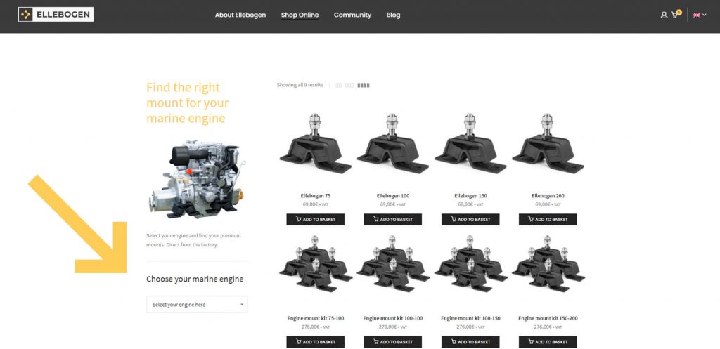
If you do not know which engine mounts correspond to your Yanmar engine, you can look for the reference number in the Yanmar engine selector section of our website: https://www.ellebogen.com/us/shop-online/
If the drive shaft is well aligned, it is important to ensure it remains firmly in place. To achieve this, we can place, for example, a wooden board under the shaft, and proceed to release the bindings between the shaft and the transmission.

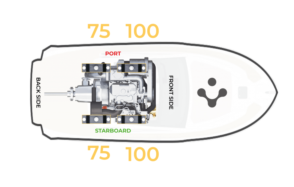
Once this step has been completed, we can start replacing the flexible engine mounts. In this case, the 3YM30 model is placed in following position over the engine mounts:
With the engine secured and ready to be raised, the fastenings of the marine engine mounts must be loosened.
With all the fixings loosened, the engine has to be lifted and the old mounts replaced with the new ones, one by one, looking at the references of on the rubber label.
In this case the owner of the boat Mr Roger Börjesson, showed excellent preparation and professionalism by carrying out this part of the process using an electrical winch.
Tip: It is recommendable that you use a double wire function at this point as this reduces the lifting speed by a half. It is especially useful to keep in mind the fact that you only need to lift the engine at a slow speed and to a height of about 10 cm.

It is also useful to note that each new engine mount has the leveling “H” at the same height as the old one. This step insures, that the driveshaft remains well aligned.

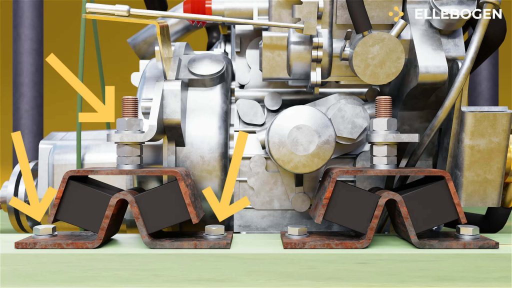
At this point it is important to note that in some installations, the levelling nut may be lower than the 12mm thick standard washer found in Ellebogen mounts.

If this is the case, we recommend using the nut from the “old” mount or using the extra low height nuts which are included in the Ellebogen flexible marine engine mounts kit.
http://ellebogen.com/elle/wp-content/downloads/extra/Extra-low-height-levelling-nuts.pdf
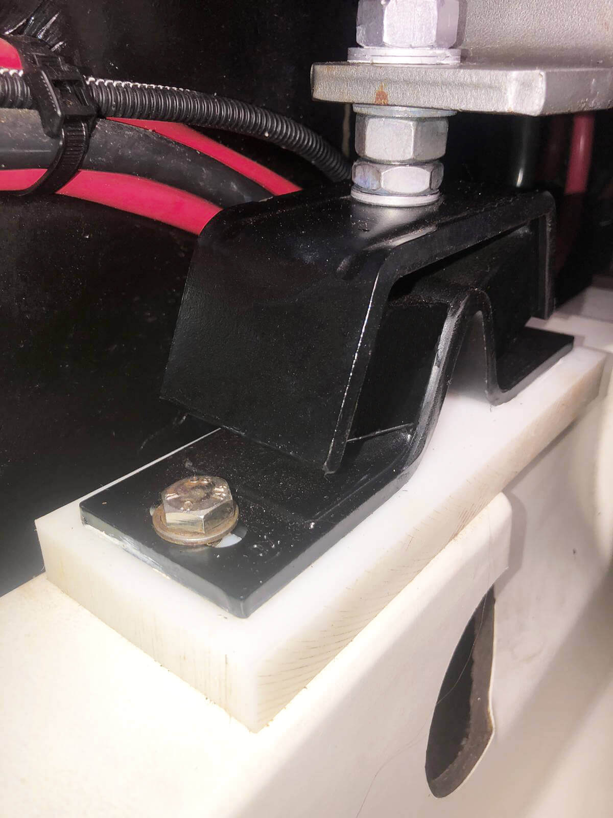
In some cases, this 2 mm height difference, may avoid problems between the driveshaft and the stern gland.
The picture on the left shows the levelling of the mount with the 12mm height nut, as can be seen the level has not been adjusted which could cause noise and vibration between the driveshaft and the stern gland.
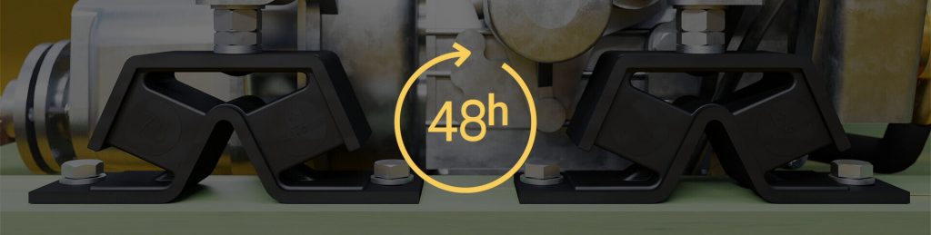
After replacing the engine mounts, the engine must be lowered and left to rest for 48 hours to in order to allow its weight to settle into its new position.
If the drive shaft is well aligned, it is important to ensure it remains firmly in place. To achieve this, we can place, for example, a wooden board under the shaft, and proceed to release the bindings between the shaft and the transmission.
Once this step has been completed, we can start replacing the flexible engine mounts. In this case, the 3YM30 model is placed in following position over the engine mounts:
Fig 4: Sketch of the position of each mount on the Yanmar 3YM30.With the engine secured and ready to be raised, the fastenings of the marine engine mounts must be loosened.
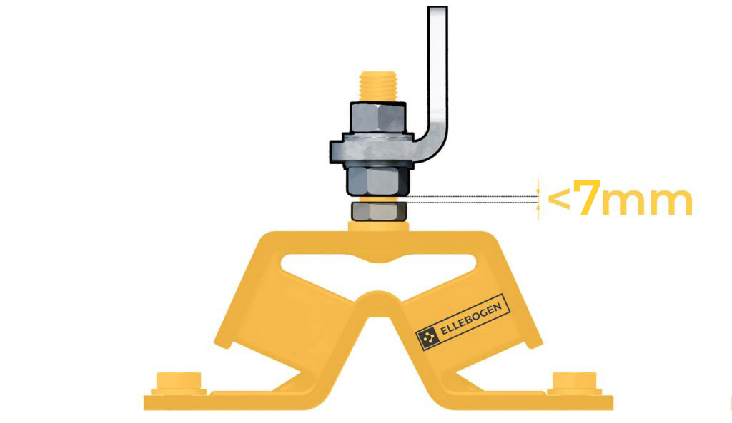
The level between the base nut and the levelling nut should not exceed 3mm. Since the propulsion force of the engine can generate repetitive stress on the height adjusters and this can cause to shear by fatigue over time.
If more elevation is needed at this stage, it can be achieved by placing a metal plate below the mount, but in general this corrective measure is not very common.
To check that the two discs are in parallel, it is important to be able to introduce a gauge of 0.003́ ́/0.07mm on all four sides and it must be able to pass through without difficulties.
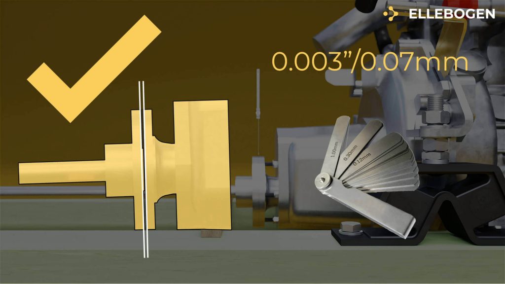
This is hard work, but it is important as misalignment of the driveshaft will cause irregularities, warping and displacement and therefore, noise and vibrations.

Ellebogen technical support guided Roger through the correct installation after which he wrote this message of thanks.

Text: In the worst case I can start the engine cold and leave it idling at a speed of 800 rpm. This would not have been possible before I changed the engine mounts. Best regards Roger Börjesson.
Thanks to Roger for this great feedback and of course, for his hard work, a real Ellebogener.